MegaSquirt-II Hall Input Modifications
In some cases, users will have trouble triggering using the Hall input circuit with some ignition modules. This may happen at lower rpms, or at higher temperatures, and seems especially prevalent for 7 or 8 pin HEI modules.
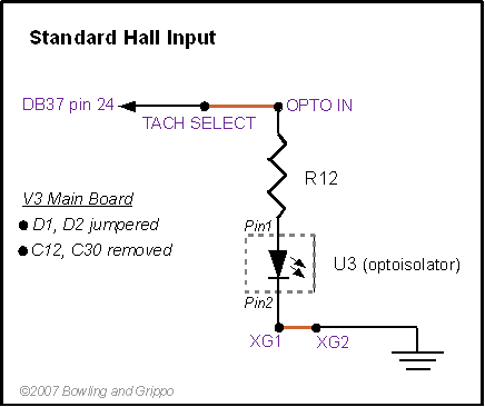
The standard Hall input circuit for the HEI and other ignition modules jumpers D1 and D2, and doesn't install C12 or C30. (In the following cases you will do the same with D1, D2, C12, and C30.) It uses the input signal to drive the optoisolator's internal LED directly to provide a trigger signal to the processor:
In cases in which the standard circuit does not trigger cleanly (because the input voltage is too low, or the signal too short), there are 3 options to improve the triggering.
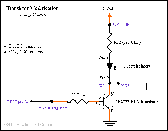
- The transistor modification is a little more complicated than the MSnS-E modification. If the MSnS-E mod is not sufficient, you can add a transistor to the circuit. Instead of using the module to sink the LED current, the transistor circuit only uses the module's signal to control the base of an NPN transistor. As a result, the module only needs to supply about 1/50th the current of the standard Hall set-up, and like the MSnS modification it has a full 5 Volts powering the LED. To set-up the transistor modification:
- Remove the jumper to OPTIO IN, and jumper OPTO IN with a wire to one of the +5V vias in the proto area,
- Remove the XG1 to XG2 jumper,
- Install a 2N2222 transistor {Digi-Key P2N2222AOS-ND or equivalent} in the proto area,
- Jumper XG1 to the collector pin (the pin on the right when the flat side is up and you are looking at the top of the case), do not jumper anything to XG2,
- Jumper the emitter pin (the pin on the left when the flat side is up and you are looking at the top of the case) to ground (Gnd) in the proto area,
- Install a 1K Ohm (1/4W) resistor in then proto area, and jumper one end to the TACH SELECT via,
- Jumper the opposite end of the resistor you just installed (not the end jumpered to TACH SELECT) to the base (middle pin) of the 2N2222 transistor.
This circuit triggers the optoisolator's LED when the signal is active, so the 'Input Ignition Capture' is the same, for example 'Rising Edge' for the HEI modules.
- The VR input circuit. The VR circuit is generally more sensitive to low voltage signals than the Hall circuit. You do have to adjust the R56 pot a dozen or so turns clockwise from the fully counter-clockwise position (see: vradjust.htm).
Note that the VR circuit on a V3 main board inverts the signal when used for a square wave signal (MicroSquirt/MS-II Sequencer does NOT invert the signal with its VR input circuit). The net effect is the same as the optoisolator in the standard circuit, so you use the same setting. For example, for the 7 or 8 pin HEI modules:
- The trigger for the VR sensor occurs on the negative to positive transition,
- This transition causes a high to low signal event from the 7 or 8 -pin module,
- The VR circuit inverts this to a low to high signal,
- So we trigger on the 'Rising Edge' ('Falling Edge' with MicroSquirt/MS-II Sequencer).
Note that the VR input circuit on MicroSquirt® and MS-II/Sequencer controllers do not invert the VR signal (or, more technically, they invert it twice), so you use the opposite edge as the trigger.
MegaSquirt® and MicroSquirt® controllers are experimental devices intended for educational purposes.
MegaSquirt® and MicroSquirt® controllers are not for sale or use on pollution controlled vehicles. Check the laws that apply in your locality to determine if using a MegaSquirt® or MicroSquirt® controller is legal for your application.
MegaSquirt® and MicroSquirt® are registered trademarks.
©2006, 2007 Al Grippo and Bruce Bowling - All rights reserved. MegaSquirt® and MicroSquirt® are registered trademarks.


