 |
| |
Q: What is the Precision Wideband Controller?
A: The Precision Wideband Controller is a controller for wide-range lambda sensors (i.e. sensors which include a separate Nernst cell and oxygen pump cell).Features include:
- Full-range operation of the pump circuit for full-range operation of the wideband sensor.
- Full-range operation of the sensor heater utilizing SEPIC switching power supply to ensure stable sensor temperature for any battery voltage.
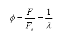
- Analytical calculation of Lambda (
) and AFR based on hydrocarbon information, water-gas equilibrium, and exhaust back pressure information.
- Automotive temperature range components used for all devices.
- Efficient circuitry eliminates the need for external heat sinking for power components.
- Stable voltage references utilized for precision.
- Extensive noise filtering on battery voltage to prevent noise entering or leaving the controller.
- Precision instrumentation amplifier used for pump current detection – best CMRR rating available.
- On-board thermocouple amplifier with cold-junction compensation for K-type thermocouples.
- On-board temperature monitor of DSP for over-temperature detection.
- CAN network interface.
- Very high-speed UART interface.
Q: There are many other Wideband Oxygen Controllers out there, why re-invent the wheel?
A. The reason for re-inventing the wheel is when the current wheel does not meet all of the needed requirements for a particular application. Read this entire document and this will become very clear.
Q: What is the difference between a Wideband Meter and a Mixture Feedback Controller?
A. When tuning an engine on the road or on a dynomometer, it is desirable to have a means of monitoring engine air-fuel ratio (AFR), which can also be expressed in terms of lambda (A mixture feedback device is used to determine the instantaneous mixture of a running engine, where these parameters are introduced back into the fueling equation in the ECU for real time injector pulse width correction. The main demand of the mixture feedback device is that it needs to be repeatable over absolutely all environmental conditions the same readings for extreme hot or freezing cold conditions.
In addition, the response function of the wideband UEGO sensors is dependent on parameters like hydrocarbon type, operating temperature, exhaust temperature, exhaust back pressure, etc. If any of these parameters change, then the controller needs to know this and be able to correct/compensate.
The Precision Wideband Controller is a mixture feedback device.
Q: How does the wideband UEGO sensor operate?
A. Before one can design hardware circuitry and control software, it helps to have an understanding of how the wideband UEGO sensor operates.
The wideband exhaust gas oxygen sensor comes in many constructional forms, but are basically similar in nature. They consist of two parts: a Nernst reference cell and an oxygen pump cell, coexisting in a package that contains a reference chamber and heater element (used to regulate the temperature of the Nernst/pump).
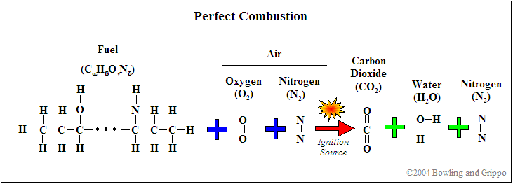
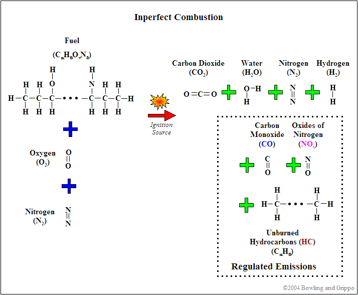
Before delving deeply in the operation of the Nernst and pump cells, it is important to understand what the sensor is actually trying to measure. To start, lets understand the chemical reactions due to combustion.
First, realize that for combustion to occur, there needs to be fuel (such as hydrocarbon) and a source of oxygenates (i.e. oxygen and/or molecules or partial molecules which contain oxygen). In addition, there are diluents which are present in the mixture but do not contribute to the actual combustion (for example, nitrogen [N2]). This holds true for any combustion event, whether inside of an internal combustion engine or a small campfire.
Second, every atom is conserved in the combustion process, so it is possible to use exhaust gas constituents to reconstruct the amount of fuel and oxygenates before combustion. If this was not the case, then wideband oxygen sensors would not be capable of determining pre-combustion air/fuel ratio.
It is possible to express the combustion event as a balance of input reactants: fuel, oxygenates, and diluents (for example gasoline mixed with air) to the resultant combustion products (i.e. the composition of exhaust gas). Note that this is a chemical balance, meaning that every element needs to be accounted for in its molecular balance, before and after the combustion event. In other words, if we know the proportions of fuel, oxygenates, and diluents entering the engine, one can determine the species composition in the exhaust gas. And we can work backwards. If we know the species in the exhaust we can determine the ratios of air and fuel (both in molar quantity and molecular mass).
Let us represent the chemical composition of the intake fuel as carbon, hydrogen, oxygen, and nitrogen, in proportion of:
C H
O
N
,
with
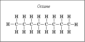
For example, octane has a molecular composition of C8H18, so there are 8 atoms of carbon and 18 atoms of hydrogen, so we have
Other fuel molecules have other compositions, obviously.
We can combine the fuel with air and write down a simple balance equation for combustion and balance for the molar quantities before and after combustion:
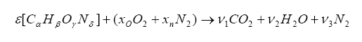
The items on the left side of the arrow represent the fuel/oxygenates/diluents entering the engine and the items on the right are the molar quantities after the combustion event. We want to solve for the unknown
, which is the molar fuel-air ratio (equivalency ratio), and the coefficients
1,
Note that we have more unknowns than equations, so we will have to use some known constraints to help us solve for the unknowns. For one, atoms are conserved (i.e. what goes in must come out), so we can immediately write the following relations (known as the element balance equations):

The solution for the balance equations (listed above) are the following:
And from this one can write the stoichiometric fuel-air mass ratio as:

Note that the stoichiometric mass air-fuel ratio is simply the reciprocal of the above equation. Also, the fuel-air equivalence ratio is defined as the actual fuel-air ratio divided by the stoichiometric fuel-air ratio (note that the reciprocal of this is defined as lambda):
Now, since we are dealing with exhaust gas (i.e. low temperature compared to the actual combustion event) and carbon-to-oxygen ratios less than unity, one can introduce CO and H2 into the balance:

It is somewhat difficult to solve this, but we know a few things can make our life easier. First, if the mixture is lean (i.e.
< 1) then
which yields the constant Kp:

where t is the temperature in Kelvins.
With this,
where:
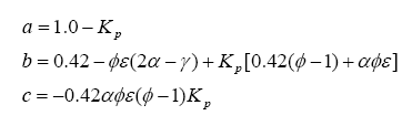
Using this result, a chart outlining the solution for each gas species can be tabulated for either lean or rich situations:

There are a few things to note in all of this. First, the hydrocarbon/fuel specified as:
C can be the combination of two or more hydrocarbons. For instance, when fuels are mixed with alcohol, the resulting mixture can be expressed as a single hydrocarbon with balanced subscripts. The same is true for water injection or nitrous oxide injection. This is a very important advantage in using a mathematical approach to determining lambda – if the fuel component changes it is possible to adapt the response of the wideband appropriately without any recalibration. This is not the case with systems that rely on a fixed wideband sensor response “curve”. And, if the wideband controller is connected to a ECU (via CAN bus) and the ECU is controlling the introduction of water or nitrous, it is possible to instantaneously adjust the lambda response curve for any ratiometric combinations of hydrocarbons. This is an important requirement for a mixture controller.
Next, one can divide the hydrocarbon/fuel expression by a constant, which will make the carbon subscript equal to one. This creates a H/C ratio, a O/C ratio, and a N/C ratio – these are often seen in the literature. For example, the fuel C8H18 (octane) can be normalized to become CH2.25, where the H/C ratio is 2.25, the O/C ratio is 0 (because there is no oxygen component) and N/C of 0 (no component), and, of course, the C subscript is 1. Another example is the fuel CH3NO2, which already has a C subscript of 1, so the H/C ratio is 3, the N/C ratio is 1 and the O/C ratio is 2. Just note that either form of expressing the fuel is identical. Note: For those who are interested in experimenting with the above equations, we have developed the program COMBAL, a PC application running under Windows. One basically enters the H/C and O/C ratios, exhaust gas equilibrium, and the target lambda, and it generates the percent moles of each of the gas species. A comparison check using the Brettschneider equation is also performed. The application can be downloaded from:
www.bgsoflex.com/pwb/combal.zip Finally, there are two other gas constituents, CO and H2, which also exist in the exhaust gas. These are from a balance known as the water-gas equilibrium – more on this later in this document, but suffice to say that it is indeed important in wideband sensor operation.
Are you confused yet? If you are, do not be concerned. All we are outlining here is that with known input fuel, diluents, and oxygenates, one can predict the gas concentrations in the exhaust. And we can go backwards – with measured gas constituents it is possible to determine the input mixture in terms of either lambda or air/fuel ratio. Go back and re-read the section a few times, it is important to understand this aspect.
There is much more to the analysis not shown here – see the Bowling & Grippo paper on the entire analytical method for the Precision Wideband Controller for more info.
Lets move on. Now lets attempt to understand the operation of the Nernst cell section of the UEGO. The Nernst cell is an electrochemical cell consisting of a solid electrolyte conductive only to oxygen ions. Attached to this electrolyte are two platinum electrodes. One electrode is exposed to atmosphere and the other is exposed to a reference chamber (more on this later).
At the electrodes, the following reactions occurs:
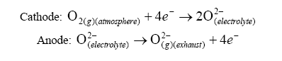
With this reaction occurring, a current can be generated. Using the Nernst equation, one can calculate the EMF produced under a no-load situation:
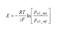
Where E is the Nerstian EMF generated,
R is the Universal Gas Constant = 8.31 J*K-1*mol-1,
T is the temperature of the cell in Kelvin,
F is the Faraday Constant = 96500 Cmol-1,
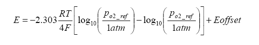
z is the electrons transported per O2 = 4.Because there is a heater maintaining the Nernst cell at an elevated temperature, a temperature gradient exists which generates an offset voltage. We can add this term to the above term, and in the process we can also simplify the calculation by converting from base e to base 10 logarithms:
Now that we know the operation of the Nernst cell, a little on the physical construction is in order. The UEGO sensor is of a “planar structure” – this means that it is in a rectangular form as opposed to a thimble or other symmetrical shape – think of a flat sandwich of components. In the sandwich, there is the Nernst electrolyte which is generally constructed from Yttria Stabilized Zirconia (YSZ), although other forms do exist. What is Yttria Stabilized Zirconia? It is Zirconia (ZrO2) with roughly three percent of moles substituted with Yttria (Y2O3). Because every two zirconium ions are replaced with yttrium, an oxygen vacancy exists – this allows adjacent oxygen ions to “jump” to these sites and at elevated temperatures this activity is the basis for EMF production.
Continuing the discussion of the planar structure, there exists an internal “diffusion cavity” – this cavity is where the sample of exhaust gas is “trapped”, as well as where the Nernst and pump sections face. How does the gas get there? By a diffusion process, the exhaust gas to be sampled enters the cavity. Not to get too “geeky” about the diffusion process, but suffice to say that there are two diffusion mechanisms:
Very, very important to note: Knudsen diffusion is temperature dependent – this means that the porosity of the test chamber (i.e. how much gas can enter/exit) depends on the sensor head temperature – this is why pumping current (described next) is different for different temperatures, as well as exhaust back pressure dependence.
- one is known as molecular diffusion, and
- the second is known as Knudsen diffusion, or “fine-pore”
Now it's pump-time! The aforementioned oxygen pump – this is what makes a run-of-the-mill oxygen sensor a true wideband unit – is really just another Nernst-type cell with an external current applied to it.
We talked about the “cavity” above where sample exhaust gas exists and on one side is the Nernst measurement cell. On the other side is the pump cell – this cell is used to transport oxygen into and out of the measurement cavity. In very simplistic terms, if the exhaust gas in the measurement cell is lean, then there is excess oxygen (lean mixtures mean excess oxygen). We can “turn on the pump” to remove oxygen from the reference cavity – and with the proper feedback monitoring of the Nernst measurement cell we can pump out just enough oxygen to achieve a stoichiometric balance (roughly when the Nernst measurement cell reads 0.45 volts or thereabouts).
The best part of all: if we monitor the pump current, we can use this to determine lambda (
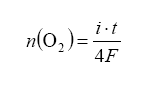
with n being the moles of O2 gas pumped, t for time and current i. To make this equation useful it should be converted to partial pressure change within the reference cavity. Also note that the diffusion (explained above) will bring in more exhaust gas over time – so what we are doing is making an equilibrium with feedback from the Nernst measurement cell dictating how much oxygen to pump away, all the while more exhaust gas is diffusing in. Note that the pressure of the exhaust gas under measurement also affects the amount of diffusion into and out of the measurement cavity – this is the famous back pressure effect.
We have explained the excess-oxygen case where the air-fuel mixture is lean. How does it operate on the oxygen-depleted side, or rich air/fuel ratio side? For this case, oxygen is ‘pumped’ into the measurement cavity simply by reverse application of current on the pump element. Feedback on the Nernst measurement cell indicates when stoichiometric equilibrium has been achieved.
Now, something should be bothering your gut right about now…
The pump cell operates on oxygen ion transport, but we are in a situation where there is no oxygen in the air-fuel mixture (i.e. we are rich). If we become much more rich, we still do not have oxygen. Super rich, and still no oxygen. How can there be a feedback situation in this case?
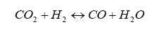
It turns out that within the diffusion measurement cavity, the following chemical reactions are occurring:
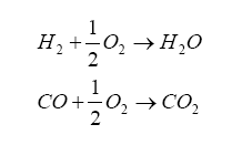
So, the oxygen pumping portion acts to introduce the oxygen into the diffusion chamber by the electrolysis decomposition of the carbon dioxide (CO2) and water (H2O) in the measuring gas. Think of it this way: we have exhaust gas trapped in the diffusion cavity which contains H2 and CO, and the oxygen pump is generating O2 – these combine to produce CO2 and water. If we have more H2 and CO in the exhaust gas, then more O2 from the pump gets converted – and, in order to increase O2 production we increase the pump current.
And it turns out that H2 and CO are present in significant amounts for a rich AFR, and can be related to lambda by the elemental balance equation for the fuel/oxygenates/diluents we derived above.

This is not exactly right, in that we are dealing with a gas balance and the pump is really an electrochemical cell (click on the links for background information on Le Châtelier's Principle for equilibrium balance rules, as well as the Ideal Gas Law), so we need the oxygen in the H2O and CO2 as donors for the reaction – this where the pump gets its oxygen. It’s a balance, and by changing the amount of current pumped into the pump we can change the balance. The balance is also driven by the water-gas reaction, discussed later on.
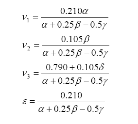
Finally, lambda (
All this says is that there are known combinations of exhaust gas quantities (either in terms of moles or in partial pressure) that directly relate to lambda. These include H2 and CO.
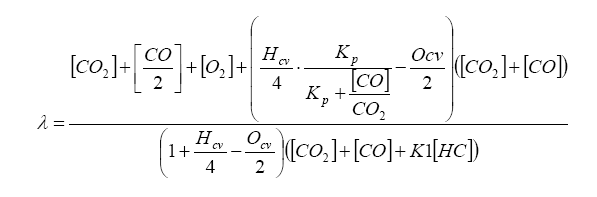
So, armed with all of this knowledge, we can write an equation relating pump current compared to exhaust gas component, then stick this into the Brettschneider equation (or a more advanced form – see the Bowling & Grippo paper). For the lean mixture side where there is excess oxygen, the pump current equation is:
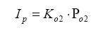
So, the required pump current Ip is simply the partial pressure of O2 in the diffusion chamber multiplied by a calibration coefficient Ko2. Remember, this is the partial pressure of oxygen, not the molar quantity, so the elemental mass needs to be involved.
To get the molar quantity, you would use the ideal gas law:
PV=nRT = NkTwhere:
P = pressure, V = volume, T = absolute temperature, n = number of moles, R = universal gas constant = 8.3145 J/mol K, N = number of molecules, k = Boltzmann constant = 1.38066 x 10⁻²³ J/K = 8.617385 x 10⁻⁵ eV/K, k = R/NA, NA = Avogadro's number = 6.0221 x 10²³ /mol For any given volume of gas (it doesn't have top be enclosed, of course) you can use the partial pressures to compute the molar quantity. That is, since we are dealing with the same volume of each gas and all are at the same temperature, V/T = nR/P is a constant for all the gases, and by substituting R and P (the partial pressure of a particular gas) you can get the rations of n - the molar amounts.
For the rich mixture side, where there is no oxygen, the sensor measures the amount of CO and H2 in the exhaust gas (partial pressure):
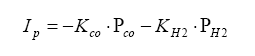
Note the minus signs. The applied pump current is reverse polarity such to make the oxygen pump an oxygen generator, not an oxygen sucker.
Also note that on the rich side, the UEGO sensor reacts to unburned hydrocarbons as well. However, in normal combustion, the amount of unburned hydrocarbons are in the parts per million region, whereas the moles of CO and H2 are substantially higher (like in the 10 – 20% range).
Q: Where does one get the sensitivity coefficients Ko2, Kco, and KH2?
A. You measure them with calibration gases. And it is important to note that the coefficients are different for each gas.There is much, much more to the whole wideband sensor operation, but the above should illustrate that there is a lot to consider in operating the sensor. Its easy to bolt a circuit together and get numbers out of it and call it correct, but it is much harder to understand the operation and compensate/correct for effects; so one should cast a critical eye on any number coming out of any wideband controller (including this one) until it has been proven accurate to some reasonable measure.
Q: Can you explain the overall circuit operation?
A. Sure! The heart of the system is the Motorola 56F8323 DSP/Controller. This is a 16-bit fixed-point DSP operating at 64 MIPs with a plethora of on-board peripherals, and it operates over the automotive temperature (-40°C to +120°C). The DSP has the usual collection of items like decoupling capacitors, crystals, etc. This DSP also has a JTAG emulator connection, allowing in-circuit board development. Core and I/O voltage is 3.3 volts. Other nifty items are an on-board 12-bit ADC, CAN, SCI, and SPI. And, there are free C compilers and debugger tools available for this device.Next in line is the 4-channel DAC, the Linear Tech LTC1458. This DAC communicates to the DSP using a standard SPI interface. The four channels each are assigned a function: channel 1 controls the heater power supply, channel 2 controls the external wideband analog output, channel 3 is used for the UEGO pump drive, and channel 4 is used for setting up a variable reference for the return path of the Nernst/pump cells in the sensor. The DAC is a 5-volt device, but its logic 1 threshold is 2.5 volts, hence the DSP can drive the DAC to a logic 1 level using 3.3V. For the “other” direction (MISO), a pair of resistors form a voltage divider.
Next is the actual sensor control. For pump and virtual ground drive, a Linear Tech LT1639 is used for both its drive current capabilities (rail-to-rail) and its capability of driving large capacitive loads. For the actual pump current detection circuit, a precision instrumentation amplifier from Burr-Brown (now Texas Instruments), the INA114 is used. This device has a superior common-mode rejection ratio, something really required in a noisy environment. The output of the INA114 is presented to the ADC in the DSPTo measure the resistance of the Nernst cell (for heater regulation), a 3 kHz squarewave is coupled via a capacitor, and its response is also capacitor-coupled and amplified, forming a synchronous rectifier. The actual DC level of the Nernst cell is buffered by an op-amp and introduced into the DSP.
The next part is the heater control. This is accomplished using a Linear Tech LT1170 switcher configured in a SEPIC topology. This switcher circuit is capable of providing up to 4 amps of continuous power, and the voltage is adjustable by the DSP from 5 to 16 volts – this range is independent of the vehicle’s electrical voltage.
The power supply consists of a Murata BNX002 noise filter on the power input. Due to low power consumption in the circuit, standard linear regulators are used for the 5.0 and 3.3 volt supplies. A precision voltage reference (REG113NA) is used to generate the mid-point voltage of 2.5 volts – this is also used as the reference of the ADC.
The input for the exhaust backpressure sensor is buffered by a National LMC6484 op-amp. A complete thermocouple amplifier and cold-junction compensation is provided by the Analog Devices AD595. The thermocouple is used to monitor exhaust temperature in order to determine the water-gas equilibrium.
The physical layer CAN transceiver is the Microchip MC2551, and there is a jumper-selectable termination resistor. The UART physical layer driver is the MAX3245, which can operate at up to 1 mbit/sec for extremely fast UART communication.
Q: Why did you use a DSP Hybrid instead of a Microcontroller?
A. This is a pretty easy question to answer – if one understands the operation of the wideband UEGO sensor (re-read the above section if it is not clear).In the last few years, DSP hybrid microcontrollers have hit the market. Simply put, they combine the best features of a Digital Signal Processor (DSP) and Microcontroller. Best features include things like multiply-accumulate operations, extended precision math, bit operation, and good on-board peripheral sets. And the cost for these devices are very, very low.
Many manufacturers offer these devices, including Texas Instruments (TMS320C28x) and Microchip (dsPIC). Motorola has offered the DSP56F80x family for some years, and have just recently came out with the 56F83xx family – this is the device which was chosen for the Precision Wideband Controller. The onboard 12-bit ADC and the free compiler is enough to sway anybody, let alone the other rich mix of peripherals and on-board flash memory – and, by the way, 64 MIPS!
One could have used a simple 8-bit Microcontroller for this application, but after all of the math (if one implements it) it would be simply exhausted. The hybrid DSP is literally two dollars more, and has plenty of horsepower for the calculations. This is the 21st century – enough of trying to squeeze code into 1K of memory and instituting massive lookup tables because the part cannot do a simple division without chewing massive clock cycles.
Q: Why take a mathematical approach in determining wideband output – why not just a simple lookup table?
A. Re-read the section under the operation of the wideband sensor, and re-read it until it sinks in. The simple curve in the Bosch LSU-4 datasheet is for a specific hydrocarbon fuel, using test gas on a bench.One can take this curve, stick it in their controller, and spit out the value based on pump current, and say it will work for all applications. Heck, why even bother sticking in this curve – just spew out any old number. No one will even know, and as long as they are getting numbers, they are happy.
As the late Garfield Willis (of EGOR fame) expressed a few years back, “it’s like playing AFR horse shoes with the blind!”
Q: Why such a complicated heater circuit?
A.Perhaps the most critical aspect of control of the wideband sensor lies in maintaining a known and constant sensor temperature. The transfer curve of the Nernst cell and oxygen pump operation is very temperature dependent. What this implies is that for a given pump current required (in order to maintain a balanced Nernst cell/oxygen pump equilibrium) will change as a function of temperature.In order to maintain a valid calibration of Nernst response, either the cell must be maintained at a constant temperature or a calibration adjust which is a function of temperature be applied in order to correct for temperature offsets, or a combination of both. This is imperative if one wants to obtain consistent and comparable results over all operational conditions. Remember, any wideband circuit will give you a number, but in order for it to be consistent the operational temperature of the sensor head must be constant.
There is more on this in the Precision Wideband Controller Hardware section.
Q: What is a SEPIC Switcher?
A. The topology of the switch mode power supply for the heater is known as SEPIC (single-ended primary inductance converter). The advantage of this topology over other options, such as a buck-boost, is that the output is the same polarity as the input (a buck-boost inverts the output). Maintaining a positive reference with respect to ground makes functions like current measurement easier. The output voltage can be higher or lower than the input voltage, and in this circuit the voltage is set by the DSP (more below). Hence, the heater voltage can be set from a range of 6 volts to 16 volts and does not depend on the input voltage. With this, the heater can be controlled in a direct and repeatable manner.
Q: Why did you choose the LT1170 Switcher for the power supply?
A. Simple answer – it is pretty much bullet proof. It handles input power overvoltage to 40 volts, reverse battery, and the output can be shorted indefinitely without damage. Since the switcher can provide over 4 amps continuous, this is a good feature indeed!
Q: How did you make the fixed-voltage LT1170 Switcher adjustable by the DSP?
A. It turns out that the LT1170, like many switchers, use a resistor divider to tap off of the output voltage, and use this as a feedback to adjust the output (voltage feedback). The junction of these two resistors want to be at 1.24 volts – if this junction is higher then the switcher adjust the PWM duty cycle to lower the output voltage, and vice-versa. The resistors values chosen yield approximately 12 volts in the switcher output.Now, if one introduces a current in this junction, they can alter the steady-state point. This is done with one of the DAC channels and a series resistance. Now, by adjusting the DAC voltage, the steady-state point will be moved and the switcher will then compensate by either increasing or decreasing the output.
This setup works exceedingly well. Heater voltage response to DAC set point changes are well within the bandwidth required for real-time heater control.
Q: What is the LTC1458 DAC, and can you explain its function?
A. The LTC1458 is a four-channel, 12-bit Digital-to-analog converter, also known as a DAC. Its purpose is to provide analog voltages as are commanded by the DSP. The DAC is used to generate the analog wideband signal, heater power supply voltage adjustment, and UEGO pump and reference control.This part is not the most inexpensive DAC out there, but its capabilities outweigh its cost, items like a built-in reference, different target ranges, and a very fast SPI interface make this a really nice device.
It is possible to use a timer channel running in a PWM (Pulse Width Modulation) mode and use external low-pass filtering to achieve a digital-to-analog converter. And the DSP has 6 PWM channels that can operate at very high speed. But, there is always a small amount of ripple, unless the low-pass filter is pretty sharp, then the problem becomes a lag in response due to all of the filtering. A DAC is pretty much instantaneous in its response to a new setpoint, and we have a really fast computation engine within the DSP, so the added cost is well worth the expense.
Q: Can you explain the Nernst and pump feedback setup?
A. The operation of the UEGO sensor basically requires reading the instantaneous Nernst generated voltage, and providing oxygen pump current which will bring the Nernst cell voltage to a target value (around 0.45 volts). Many systems employ an analog system that adjusts the pump current in a feedback loop. Often, a PID (Proportional-Integral-Differential) control loop is used, with the proportional part relating to how far off the Nernst cell voltage is from the target 0.45 volts, the integral part is used to compensate for the lag and the offset in the pump cell, and the differential part used to control the ramping of the pump based on the rate of change of Nernst response.An analog solution works well, but it is “tuned” for a particular response of a sensor. Different sensor manufacturers have different feedback response (transfer function), so to change sensor head type would require hardware PID loop changes. Another implementation method is to provide digital pump control, where the analog voltage of the Nernst cell is digitized and manipulated in software, and a reverse operation (DAC) used to control the pump voltage (and hence current).
Using software to maintain the feedback loop opens up an exciting chance to experiment with different control algorithms. Since this is an experimental wideband controller, making the loops in software will allow the implementation of different feedback techniques. A few that come to mind are:
So, those who like to experiment should prepare to have some real fun – we have fast hardware and a computation engine that we can really do anything from the simple to the ultra-complex. And we will all earn something in the process.
- Simple brute-force pump current control based on Nernst cell voltage. This could be implemented in simple code, or as a lookup table of pump current setpoints compared to Nernst voltage.
- Digital PID loop. It is really easy to implement a digital form of a PID loop, where all of the parameters are adjustable in software. And with a DSP it is really easy to implement a recursive version of a PID loop:

Yi = Current pump voltage output,
Yi-1 = Previous pump voltage,
ei = Current error of Nernst cell reading from the target 0.45 volts,
Kp = Proportional PID term,
Ki = Integral PID term,
Kd = Derivative term.This form of the PID control loop is optimum for a DSP, which is designed to perform multiply/accumulate operations in a single clock cycle. Also note that the terms A1, A2, and A3 are generated only once (unless the PID parameters change), so the only real calculation is the recursive relation with Yi.
- Exotic filter implementations, like a predictor-corrector structure, Least-Mean-Square, or Kalman filter. We have the horsepower for implementation of any of these.
Q: How is the Nernst cell’s resistance measured?
A. This is measured by using a 3-kHz squarewave superimposed on the Nernst cell with a fixed amplitude. The resulting level of this waveform can be used to determine internal resistance using Ohm’s law. More on this is in the next section, but here is what the waveform looks like:

Q: Why is measuring the Nernst cell’s resistance so important?
A. Accurate temperature control of the wideband UEGO probe is an absolute requirement during operation. Changes in UEGO probe temperature will result in a change in required pump current (from the difference in diffusion in and out of the measurement cavity), so monitoring the temperature allow for corrections to be applied to the measurements. The LSU probe does not have any form of direct temperature measurement (i.e. thermistor, etc.). However, monitoring the resistance of the reference cell yields a close representation of the probe temperature - the resistance of the reference cell varies with temperature. The Nernst reference cell has a high resistance at low temperatures (i.e. ambient temperatures) and a resistance of approximately 80-100 ohms at normal operating temperature. So, by monitoring the internal resistance of the reference cell it is possible to determine an accurate UEGO probe temperature, without the need of an external temperature sensor element.There are several methods available to measure the resistance of the reference cell, including disabling the pump circuit and applying a known constant current across the reference cell and measuring the resultant voltage, finally re-enabling the pump circuit. This method requires several analog switches to apply the current and re-establish the pump servo circuit when done. Also, if a bias is applied to the Nernst cell, then an opposite polarity current with the same duration needs to be applied in order to “reset” the polarization on the cell. The one problem with this method is that it is “intrusive” to the feedback loop of the Nernst/pump.
Another method is to apply a high-frequency waveform to the pump circuit and measure the resultant deviation in EMF. The reference cell's resistance is determined by AC-coupling a square wave of known amplitude and frequency via a series resistance, and measuring the resultant AC waveform's amplitude. This waveform is always present, and since it is at a high frequency with respect to the response of the Nernst/pump feedback loop, it essentially averages out. This is the method employed in the PWB.
Circuit operation is very simple. A known square-wave source of 5 volts peak-to-peak and at a frequency of 1 to 3 kHz (generated by the DSP) is capacitively coupled to the reference cell positive terminal. Overall current is limited by a series resistance (plus Ri internal resistance) to 500 microamps peak to peak, or
250 microamps around the Vbias point (Vbias is set to 2.5 volts to allow for bi-polar pump operation) - this value meets the specification outlined in the Bosch LSU 4.2 data sheet. The alternating current signal generates a corresponding alternating voltage with value based on the internal resistance Ri. For example, if Ri = 100 ohms, then 500 microamps (P-P) multiplied by 100 ohms yields 50 millivolts p-p, or
To measure the voltage, a capacitor is used to block the DC offset (i.e. reference cell voltage) and pass the alternating signal. A gain stage is introduced and the voltage is fed into a A/D port on a processor. Note that this signal is an AC signal, so ADC sampling needs to correlate with the polarity of applied square wave signal – this is known as synchronous rectification. An alternative method would be to use a bridge rectifier circuit to recover the positive/negative swings and then filter before application to the ADC channel.
A picture is worth a ton of words:

Q: Explain the pump control circuit – why use two DACs?
A. The general implementation of the pump circuit is to simply bias the pump/Nernst return to a mid-point voltage. For example, for a circuit using 5 volts for full swing, a mid-point bias of 2.5 volts or thereabouts is often used – this mid-point bias is applied to the Nernst/pump return. Therefore, the pump control voltage (feedback) can range to a theoretical -2.5V to +2.5 volts (if the bias is chosen to be 2.5 volts). This control voltage generates a current flow in the pump.Lets take a look at the equation for pump voltage around the loop:

Where:
Rsense is the sense resistor for detecting pump current,
Rseries is all other series resistances in the pump loop. For instance, small values of series resistance is often added to unity-gain op-amp drives (i.e. wide bandwidth op-amps) in order to prevent oscillation,
Ipump = Pump current,
Vp = “Polarizing Voltage” of the pump cell – this is a voltage needed to polarize the pump cell in order to source or sink oxygen. Nominal values for Vp are +450 mV for oxygen sink and –350 mV for oxygen source.
So, the pump drive has to first overcome the polarization effect of the pump cell, then its current will be dictated by the series resistance and the applied pump potential (Vpump_loop_voltage). Using extreme values for Rsense and Rseries, and the fact that op-amps typically do not drive at full current when they are very close to the supply rails (i.e. Vsat saturation voltage, typically around 100 to 200 mV depending on op-amp operating temperature and type.) one can determine “comfortable” values of pump current of
This range is sufficient for many applications – however, for boosted operation (i.e. turbo/supercharger applications) the (possible) increased exhaust back pressure leads to a decrease in sensor response – this implies that more pump current is needed to achieve the same sensor reading.
In order to ensure that sufficient pump current is available for all operating conditions and sensor applications, the voltage of the mid-point (Nernst/pump return) is set by a voltage DAC (Digital-to-Analog Converter). The pump voltage terminal is driven by another DAC channel. So, with this arrangement, it is possible to apply close to
Note that the
In addition, having a “movable” mid-point reference has an additional benefit. For measuring pump current, the voltage across resistor Rsense is detected by the INA114 instrumentation amplifier. It is a well known fact that best common-mode rejection is obtained when the input bias currents are very close – this occurs when the voltage difference across the Rsense resistor is equidistant to the instrumentation amplifier mid-point potential (think symmetry in the circuit). In this circuit, the mid-point potential for the INA114 is 2.5 volts – so it is desirable to adjust the two DAC values such that the actual voltage on one side of Rsense and the other side of Rsense are the same delta from the 2.5 volt bias.
Q: Why use the INA114 Instrumentation Amplifier – why so complicated?
A. A: It turns out that this device makes the system simpler and much more accurate. The common form of measuring the pump current of the UEGO sensor is to place a known resistance in series with the current flow and detect the voltage drop across this resistor. A common method of detecting the voltage difference is to use an op-amp configured as a differential amplifier, with the output being the difference between the two input voltages multiplied by a gain.What we are after is a difference measurement between the voltage present on the current sense resistor. The issue here is that we want to measure the difference without any influence on the actual voltages. This leads to the parameter common-mode rejection ratio (CMRR). This is a measure of how well the amplifier rejects common voltages compared to the differential voltage – usually in units of dB. Larger CMRR values means that common-mode voltages have less influence on the measurement of differential voltage.
A typical op-amp (like a LMC6484 or equivalent) has a CMRR value of 60 dB at a gain of 1. The INA114 instrumentation amplifier has a CMRR of 96 dB at a gain of 1 typical.
Additionally, an instrumentation amplifier configuration utilizes two unity-gain op-amps as buffers to the input terminals – this increases input impedance and decreases bias current effects as compared to the traditional 4-resistor differential amplifier configuration.
The INA114BU is very easy to use. Just one resistor is used to set the gain. With a traditional differential amplifier topology, four resistor are required and these resistors need to be matched to 1 percent or better – or the result is unequal bias currents and resultant measurement error. This matching needs to be the same for all temperatures – unequal heating can cause the tolerance to drift. Simply put, the INA114BU defines the word “Precision” in the Precision Wideband Controller. This is a very critical component of the controller, and its price is well worth the accuracy.
Q: The power supply section seems complicated – why?
A. The power supply is really very simple. The +12V battery comes in on signal 12VRAW through a SMT fuse and engine ground is on signal 12VRET. This is introduced into a noise filter BNX002 (Murata), eliminating the majority of vehicle noise and spikes. It also keeps out the high-frequency switcher noise generated by the heater power supply from contaminating the vehicle supply. The 12V_CLEAN is the signal line to the heater switcher supply – it is not reverse protected because the switcher power supply already has reverse polarity protection. The 12V_THERM signal is the power supply for the thermocouple amplifier.There is a 5-volt regulator of the standard LM2940 type. The diode across the output to the input of the LM2940 provides protection to the regulator in case the input supply suddenly drops off. From here the 5-volt output is protected by a Polyfuse fuse. The fuse is a resettable type, and provides protection for pretty much the entire circuit (including the other voltages). The 5 volts is regulated to 3.3V for the supply for the DSP core.
In addition, a precision 2.5 volt reference supply is provided by the REG113NA-2.5 regulator. This is a special regulator that possesses very low noise characteristics and very high stability – and we need both. This is used for both the mid-point bias voltages for the 5-volt op-amp circuits and the reference high voltage supply for the ADC.
Q: Why is there a Thermocouple Amp in the circuit?
A. The use of the thermocouple is used to detect the temperature of the exhaust gas. But the reason is not to monitor the temperature for optimum mixture tuning. It turns out that to determine the gas composition of the exhaust requires knowledge of the exhaust gas temperature.There is more information in the K-type thermocouple section.
Q: Why did you choose the AD595 Thermocouple Amplifier?
A. The AD595 Thermocouple Amplifier, made by Analog Devices, incorporates cold-junction compensation for K-type thermocouples.For more information, see the K-type thermocouple section.
Q: Where is the Analog-to-Digital Converter, and what is its resolution?
A. This one is simple – it is a 12-bit ADC integrated within the 56F8323 DSP. It should be noted that Motorola has employed significant design emphasis to the integrated linearity of the ADC, to the point that they bring out the mid-point reference of the ADC in order for external compensation (i.e. capacitor).
Q: What is a CAN Physical Layer and why do we need it?
A. CAN, or Controller-Area-Network, is a serial networking protocol which was designed by Bosch for use in automotive environments. CAN offers a robust and easy to use networking infrastructure.Why does the Precision Wideband Controller need a network like CAN? In the implementation of the controller, the use of an analytical method of determination of lambda (
For example, when injecting nitrous, the chemical balance with respect to the hydrocarbon ratios are altered – this will lead to inaccurate calculation of lambda unless it is accounted for. The integration of the controller will provide information back to the Precision Wideband Controller (using CAN) on any hydrocarbon change, in real-time.
So if the controller knows that nitrous (for example) has been introduced, it can send a CAN message frame to the Precision Wideband Controller on this fact, which can account for the change in hydrocarbon ratios in the calculation of lambda. Same goes for water injection – this changes the hydrocarbon ratio by displacement and chemical combination in the combustion process.
This is yet another example of the difference between a wideband meter and a real-time mixture controller!
Q: Explain the Serial UART Interface – anything special here?
A. Of course there is -:) The physical layer chip can run at speeds in excess of 1 Mbit/sec! So, very high speed serial datalogging to external computers (i.e. PC) is now possible.
Q: Why are you not using the calibration resistor contained in the sensor?
A. Most of the UEGO sensors, most notably the NGK and Bosch, include a calibration resistor in the wiring harness. The resistor is used in OEM applications for determining calibration, such that the sensor can be installed in mass production without interaction.The “problem” with the resistor lies mainly in the fact that it is buried in the wiring connector, so the mating connector is a requirement in order to use calibration resistor. With all of the different target vehicles that use the UEGO sensor, the result is a plethora of connector versions, and each is unique.
In addition, in the configuration used by Bosch, the calibration resistor is connected in parallel to a known internal resistor (61.9 ohms), forming a new resistance in the 30 to 100 ohm range. This resistance is used to determine pump current in a differential amplifier mode. But the resistor is buried in the connector harness, and aging of the resistance will change the calibration. In addition, with the extra wiring to include the resistor into the circuit, there is more chance of inducing common-mode noise.
In order to eliminate the requirement for a mating connector for the particular sensor in use, we chose instead to use a fixed pump current measurement resistor (61.9 ohms). Using this known value, and using a free air measurement (that has been corrected for altitude/vapor pressure effects) the conversion required from pump current to lambda (
For more details see the Calibrating the Sensor section.
Q: In general, how does one calibrate a wideband sensor?
A. Calibration of the wideband UEGO sensors is pretty easy, but it requires a known precision gas of certain mixtures. You will want a set up gas mixtures that represent the lean, rich, and stoichiometric measurement. The actual flow bench is pretty simple to build – just squirt some test gas over the sensor as shown in the following illustration:

There really is not much more to it than this. Obtain a mixture of test gas and regulate down to a flow of approximately 2 liters per minute. Using a tee fitting arrangement, pass the gas over the sensor. Set the pump current such to make the Nernst cell voltage 0.45 volts – this current (Ipump) corresponds to the diffusion constant for the partial pressure of gas in the cylinder.
For more details see the Calibrating the Sensor section.
Q. How do I purchase a wide band oxygen sensor?
A. VolksWagen dealers in North America sell the Bosch LSU4 sensor for a very reasonable price (~$30). At the moment this sensor is only inexpensive when purchased in North America. It is Bosch 0 258 007 057 or 0 258 007 058 (these are the same sensor, but they have different length leads), purchased as a VW part # 021-906-262-B. There are many more LSU4 purchasing details here.
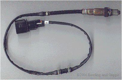
Q. How do I connect the wires to the sensor?
A. The Bosch LSU4 Wide Band Sensor has 6 wires into the connector. These are connected to the 20-pin Mini-Fit Jr. connector on the Precision Wideband Controller as follows:The illustration shows the pin-outs for the LSU4 sensor (Bosch part number is 0 258 007 057), as well as the other connections for the 20-pin Mini-Fit Jr. connector on the Precision Wideband Controller. The pin numbers are imprinted in the connector shell.
- Vs - (black) - to pins 10/11
- Rcal - (green) - not used with PWC
- H+ - (gray) - to pins 6/15
- H- - (white) - to pins 7/14
- Vs/Ip - (yellow) - to pins 9/12
- Ip - (red) - to pins 8/13

Q. Are you using the virtual ground to control the pump current, or are you driving the pump current via another DAC?
A. One DAC channel drives the virtual ground, and another DAC channel drives the actual pump. By setting the DAC voltage values one can obtain a (theoretical)
Q. How is the impedance sense coupled and sampled on the Nernst cell?
A. All of this is in the writeup coming out, but in short it is a 3 kHz 5Vp-p square wave capacitively-coupled and current limited into the cell (forming a voltage divider) and detected by another capacitively-coupled circuit with a gain stage is fed into an ADC channel. The DSP generates the 3 kHz waveform by bit-banging, and the ADC sampling is correlated to this. Thus, a synchronous rectifier circuit is created: set the bit high, enable ADC, read, set bit low, enable ADC, read ADC, then subtract the two values, and convert to resistance. It's that easy.This waveform is always applied to the Nernst cell, but since the ADC is correlated to when the signal is high or low, the square wave signal can be factored out of the actual Nernst response by a simple subtraction. And, the frequency is high compared to the actual Nernst response so it is effectively averaged out (i.e. any pump effects of the Nernst cell are averaged).
The method works wonderfully - it can detect internal Nernst resistance to an accuracy of one ohm. Bruce has tried it with fixed resistors and thermistors and it always yields the correct value.
BTW, this is the method used in the high-end meters like ETAS, and is also described in the LSU4 data sheet specifications.
* We dedicate the Precision Wideband Controller to the memory of Garfield Willis.. Garfield was instrumental in early research and development of the EGOR wideband controller.